# Nokia Mpls
### SLA Meaning (Service Level Agreements)

Some applications, such as domain name system ( DNS) and simple network management protocol (SNMP) , use UDP because they only require a simple datagram transfer. Other applications, such as Reliable transfer protocol ( RTP) , use UDP to avoid the overhead of TCP and because there is no benefit in the retransmission of lost packet for applications that use RTP.
### Encapsulation
### Data Encapsulation
### End to End Frame Transfer
### 7750 SR Family
The 7750 SR-12 is the largest 7750 SR and has 12 front-access card slots. Two card slots are dedicated for redundant common equipment. Each slot holds one Switch Fabric/Control Proccessor Module ( SF/CPM). Only one SF/CPM is required for operation. A second SF/CPM provides complete redundancy of the fabric and the control proccessors. There are two switch fabric options: 200 Gb/s and 400 Gb/s full-dublex throughput.
When two 7750 SR, SF/CPM are installed, the traffic load is shared across the switch fabrics. Two 200 Gb/s , 400 Gb/s fabrics provide 400 Gb/s/800 Gb/s of non-redundant full-dublex throughout or 200 Gb/s/400 Gb/s of fully redundant, full dublex throughput. \
The remaining 10 slots are used for Input/output Module (IOM) base boards. The backplane supports 40Gb/s full-dublex throughput to each IOM slot
The 7750 SR-7 chassis is fully redundant system and has 7 front-access slots. Two card slots are dedicated for redundant common equipment, each of which holds one SF/CPM. The remaining five slots are used for IOM base boards.\
The 7750 SR-1 has the management,switch fabric and one IOM base board integrated into the chassis. The 7750 SR-1 has an integrated switching system with 20 Gb/s fully dublex throughput and can accommodate two Media Dependent Adapters(MDA) for physical interfaces. The 7750 \
SR-1 is a small form factor switch for installations that need the many 7750 SR service capability but with less interface and protocol scaling requirements.
### 7450 ESS Family
The 7450 ESS-1 has the management, switch fabric and one IOM base board integrated into the chassis. The 7450 ESS-1 has an integrated switching system with 20 Gb/s full-dublex throughput and can accomodate two MDAs for physical interfaces\
The 7450 ESS-7 chassis is a fully redundant system and has 7 front-access slots. Two card slots are dedicated for redundant common equipment, each of which holds one SF/CPM. The remaining five slots are used for IOM base boards. The total switching capability for the 7450 ESS-7 of 100 Gb/s is limited by the IOM capability despite the switching fabric supporting up to 200 Gb/s
### Data Plane Operation
The data plane operation occurs after the control plane has built the forwarding information and stored the data in the IOM.
1\) Data from the remote network/customer site ingress through the MDAs, where the data is formatted (internal format)\
2\) The data is then processed in the I/O module where the decision the switch occurs ( Layer 2 / Layer 3 forwarding information lookup)\
3\) The data packets are sent to the switch fabric.\
4\) The switch fabric then forwards the data to appropriate IOM.\
5\) The IOM sends the data to the appropriate MDA.
### Control Plane Operation
Control messages ingress the 7750 SR and 7450 ESS in a way that is similar to the data packets. except that the control messages are processed further by the control plane.
### Ingressing the Router
### Egressing the Router
### Compact Flash
### Basic Boot Component
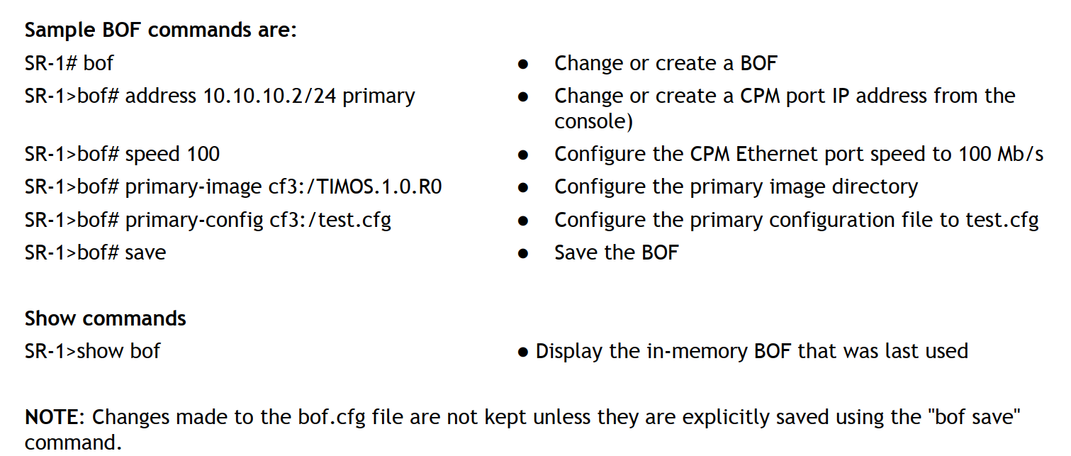
Uses a Bof to configure the system.\
Bof is stored in the compact flash CF3\
Other component required for startup
* Boot loader
* Bof configuration file
* TİMOS-m.n.Y.Z software image file
* Default config file
The image file is the software that is used to run on the 7750 SR and the 7450 ESS. This software is developed by the development team is tagged with a release number. The software contains all of the features that are required to configure and run protocols on the 7750 SR and 7450 ESS
All of the commands are case-sensitive.

The 7750 SR allows you to provision slots, IOMs, MDAs and ports before or after they are physically installed. \
You can also optionally specify the line cards that can be installed in a slot and the MDAs that can be installed in an IOM.\
A line card or MDA will not initialize unless the installed type matches the allowed type.\
Provision the 7750 SR hardware in the following sequence.\
1\) Choose a chassis slot and provision the IOM type for the slot.\
2\) Choose an MDA slot and specify the MDA type for the slot.\
3\) Choose a port and configure the port.\
IOMs,MDAs,and ports must be enabled with no shutdown command.
### BOF Parameters
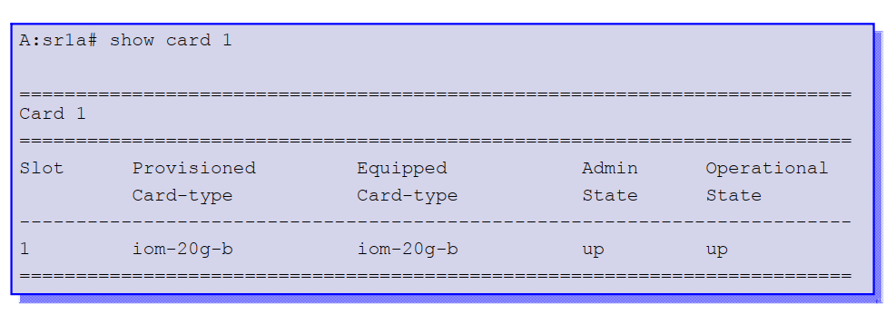
### show card
### Show MDA
Provisioned = Tedarik edilmiş, sağlanmış, karşılamak
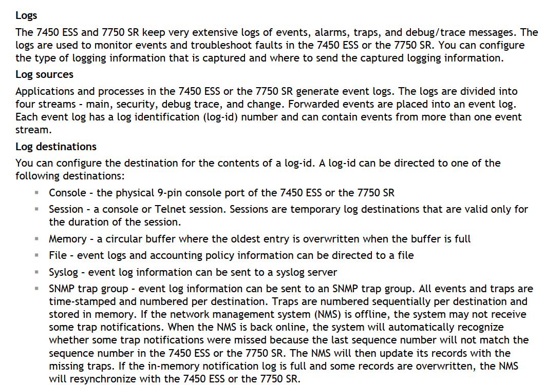
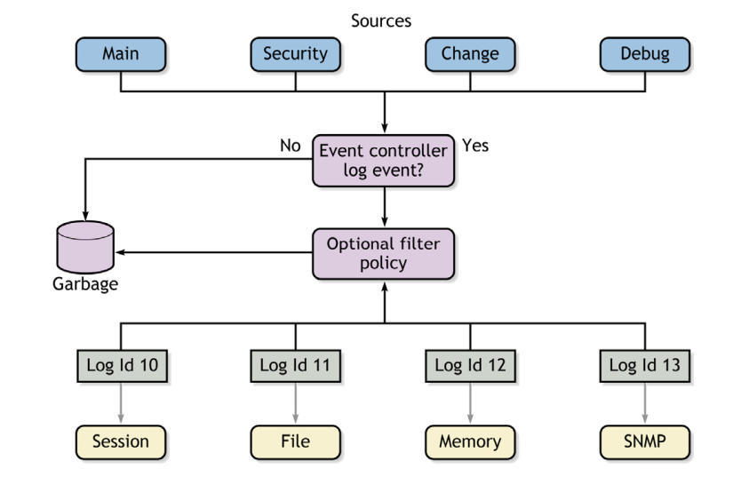
### Logs
time-stamped = zaman mühürlü
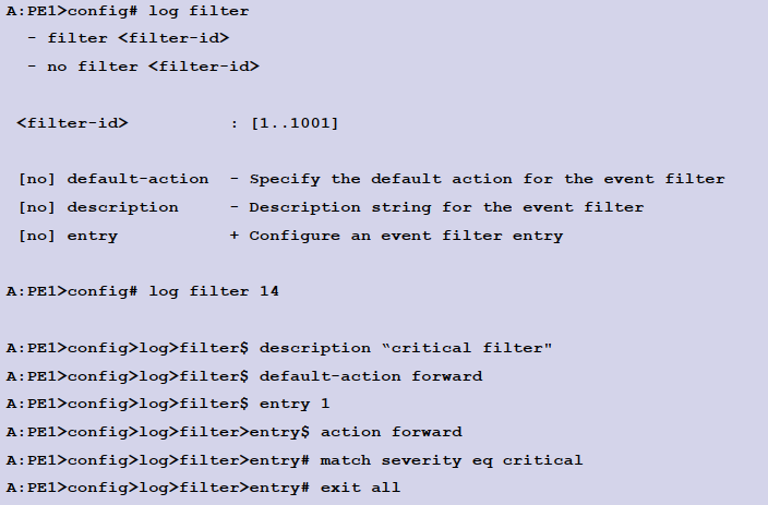
### Configuring Logs


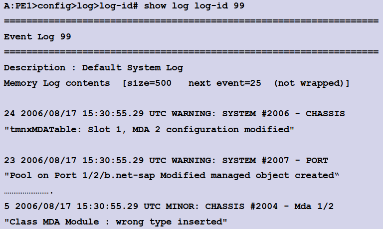
### Default Alarm Logs
Show log log-id 99 applications chassis command displays all alarms that are logged in the router.