# Mpls
The maximum frame size (in bytes) that is permitted over a certain link or service\
Oversized frames arriving at a layer 2 interface are not fragmented, but simply discarded\
For an Ip/Mpls network, the following MTU entities must be considered:\
1\) Service MTU\
2\) Access port, or SAP MTU\
3\) SDP path MTU\
4\) Network port MTU
### Service MTU
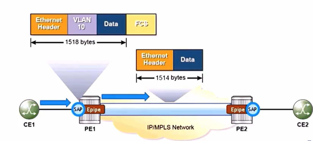
Service MTU defines the maximum customer payload that can be carried end to end in a service.\
The default MTU for an **ethernet VPN** service is **1514 bytes.**\
1514 = 1500 bytes (payload) + 14 bytes (DLC header)\
FCS is not carried but recalculated at the far end.
### SAP MTU
Derived from the physical access port MTU\
İncludes VLAN tags arriving at the SAP\
Vlan tags are service-delimiting by default, thus stripped on arrival \
The SAP MTU must be >= service MTU + Vlan encapsulation for the SAP to be operationally up.
### SAP MTU Calculation
Null encapsulation default MTU is 1514\
Dot1q encapsulation default MTU is 1514+4 = 1518 \
Q-in-Q encapsulation default MTU is 1514 + 4 + = 1522

### SDP Path and Network Port MTU
The SDP path MTU defines the maximum payload size that can be carried in the SDP transport tunnel.
* By default, it is derived from the network port.
* SDP path MTU = egress network port MTU -SDP encapsulation
* SPD path MTU >= service MTU
### SDP Path MTU Calculation
For a gigabit ethernet network port with a default MTU of 9212
#### If SDP uses MPLS encapsulation
#### If SDP uses Gre encapsulation
### Epipe MTU Case Study
Epipe services ID 50 is configured between PE1 and PE2 with a service MTU of 1514 bytes. \
The customer sites connect to the PE routers using dot1q ethernet encapsulation\
The SDP between the PE routers uses RSVP-signaled LSPs for transport.
New requirement for epipe 50 to support a maximum customer packet size of 5000 bytes.
Service Mtu değeri 1514 byte. Sap Mtu değeri vlan tag'i de dahil olduğu içij 4 byte daha eklenmiş hali olan 1518 byte.
SDP, Mpls encapsulation kullandığı için MTU değeri 9190.
1/1/1 portu SAP portu 1518 byte, 1/1/2 portu Network portu.
### SDP (Service Distribution Point)
A service distribution (SDP) defines a transport tunnel between the PE routers.\
A SDP is bound to a VPLS service using either a spoke or a mesh SDP.\
The SDP binding type determines how flooded traffic is transmitted.
### Spoke SDP Flooding Behavior
Flooded traffic received on a spoke SDP is replicated on all other spoke SDPs,mesh SDPs and local SAPs.
### Mesh SDP Flooding Behavior
Flooded traffic received on a mesh SDP is replicated on all other spoke SDPs and local SAPs.
* Not replicated on other mesh SDPs.


### VPLS Flooding Behavior
Vpls provides a layer 2 multipoint connectivity\
Traffic is forwarded based on destination Mac address.\
Each PE dynamically builds its forwarding database (FDB) based on the source MAC address in traffic offered to the VPLS\
VPLS forwarding behavior depends on the type of traffic sent.
### Known Unicast Traffic
Traffic destined to a known unicast address is sent only to the destination.
* A known destination is one that is present in the FDB
### Broadcast, Unknown Unicast and Multicast (BUM) Traffic
Traffic destined to a BUM address is flooded to all local SAPs and remote PEs in the service.
* In a basic VPLS, the SDP is bound to the service as a mesh SDP
### Mac Learning in a VPLS
* Vpls is fully meshed

### Mac Aging
FDB entry is added with an age of 0\
Age resets when receiving a packet with a matching source mac address.\
Age increase during inactive flow\
FDB entry is removed if age is greater than the age timer


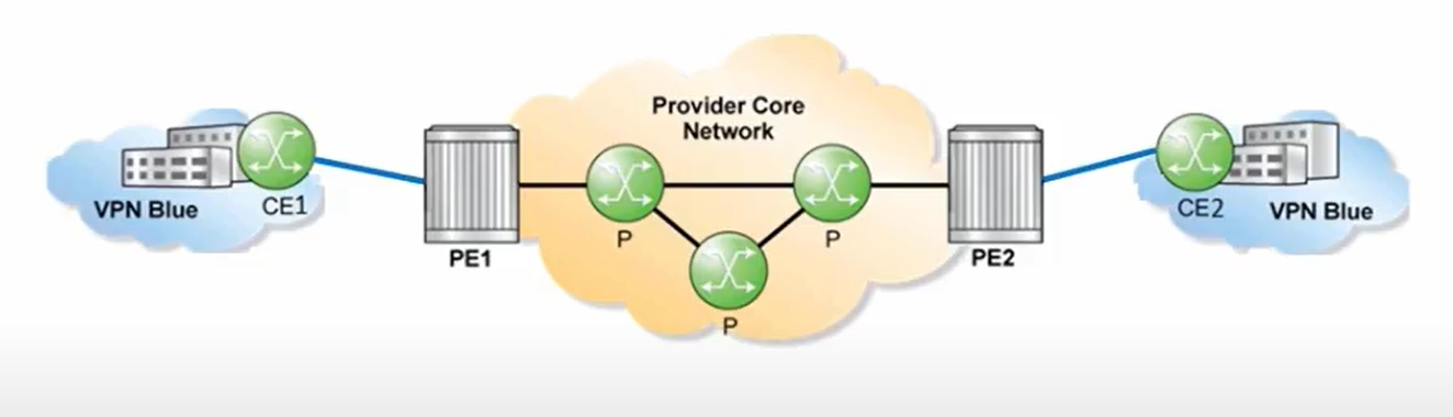
### VPRN (Virtual Private Routed Network)
* Connects multiple sites in a single routed domain over the provider network.
* The provider network is invisible to customer
* The vprn appears as a virtual IP router.
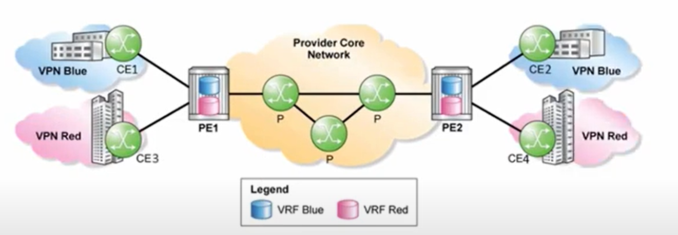
#### Virtual Routing and Forwarding (VRF) Table
* Contains customer routes for the VPRN
* A PE maintains a VRF for each provisioned VPRN service
### Distribution of Customer Routes in VPRN
* CE-to-PE Routing
* The CE router distributes routes to the local PE router, the PE router stores them in the VRF for the VPRN service.
PE-to-PE Routing
* MP-BGP distributes customer routes between PE routers
PE-to-CE Routing
* The PE router distributes the VRF routes learned from remote PE routers to the local CE routers.
#### CE-to-PE Routing
* The PE router peers with the CE router to exchange customer routes
* Customer routes are kept in the VRF for the VPRN service
* CE is effectively peering with the VRF on the PE routes.
The CE router can use static routes, RIP,ISIS,OSPF or eBGP to exchange routes with the VRF
#### PE-to-PE Routing: MP-BGP
A single instance of MP-BGP handles route exchange for all VPRN services.\
The RD (Route Distinguisher) is used to distinguish between customer routes from different VPRN services.\
Each VPRN is configured with a unique RD\
The RD is a added to the IPv4 prefix to create a VPN-İpv4 prefix.
#### PE-to-PE Routing: Route Target (RT)
Question: How does receiving PE determine which routes belong to which RF ?
The route Target (RT) is a bgp extended community added by the advertising PE when the route is exported from the VRF into MP-BGP
* The receiving PE uses the RT to select the routes that will be imported into a VRF
#### PE-to-CE Routing
VPN routes received from remote PEs are added to the VRFs and need to be advertised to local CE routes.
* A routing protocol or a static route is used for PE-CE routing
{% embed url="" %}